
Protective Film Peeling & Rewinding Device for Metal Coil Lines
Remove surface-protection film during uncoiling, leveling, or feeding and collect it into a controlled roll. Henli configures the take-up width, drive behavior, and mounting structure around your material and production line.
Automatic film peeling for stainless steel, aluminum and copper coil: the film is peeled at the same speed as the strip moves and wound under adjustable torque.
Built around your line: share the strip width, maximum line speed, target installation position, and material travel direction before quotation.
How the protective film peeling device works 45-second demonstration
Illustrative 3D demonstration of HENLI protective film peeling and rewinding units on a mirror stainless steel stamping line.

The unit up close
A Take-Up Shaft, a Gear Motor and Its Own Torque Control
This standalone unit shows the parts every configuration shares: a take-up shaft for the peeled film, a gear motor and coupling that drive it, and a control box where the winding torque is set. The same function is built onto decoilers, levelers and feeders.
- Take-up shaft. Collects the peeled film into a manageable roll; the shaft and roll size are matched to the decoiler, coil and film.
- Gear motor and coupling. Drive the shaft so the film is peeled at the same speed as the strip moves.
- Control box. Set the winding torque for the film here; nothing is added to the press or feeder program.
- Films it handles. PE, PVC and laser-cutting protective film, plus interleaf paper or release liner, up to 1300 mm wide.
- Made by HENLI. Built in HENLI's own factory; standard configurations usually ship within 7 days, with a 2-year warranty.
Send the material width, maximum line speed, an installation photo and the strip direction; Henli matches the shaft, drive and bracket to your line.
Selection logic
Four inputs define the right take-up configuration
The device is not sold as one fixed model. Henli matches the structure and drive setup to the metal strip and the place where the protective film leaves the line.
Material width
Confirm the maximum strip width so the take-up span and support structure fit the film.
Maximum line speed
Use the real production speed to match the drive and the usable winding behavior.
Installation target
Choose a standalone floor unit or show the decoiler, leveler, straightener, or feeder to be fitted.
Strip travel direction
Confirm the material path so the support bracket and take-up direction can be prepared correctly.
Working principle
Peel, take up, adjust, and collect
Buyers also call it a protective film peeler, an automatic film peeling decoiler attachment or a PE film removal system, and it works on decoilers and uncoilers as well as levelers and feeders. The unit uses its own controller and adjustable winding torque. It does not need to become another programming task for the press operator.
Choose the peeling point
Separate the film where the strip path provides a clean route to the take-up shaft.
Guide film to the shaft
Lead the removed protective film away from the metal strip and onto the collection shaft.
Set suitable torque
Adjust the winding pull to suit the film. If the pull is excessive, reduce the setting.
Collect the waste film
Wind the loose film into a manageable roll while the metal strip continues to downstream processing.
Installation formats
One function, adapted to three common line layouts
The buyer chooses the installation location. Henli chooses the practical take-up structure after reviewing the width, speed, photo, and strip direction.
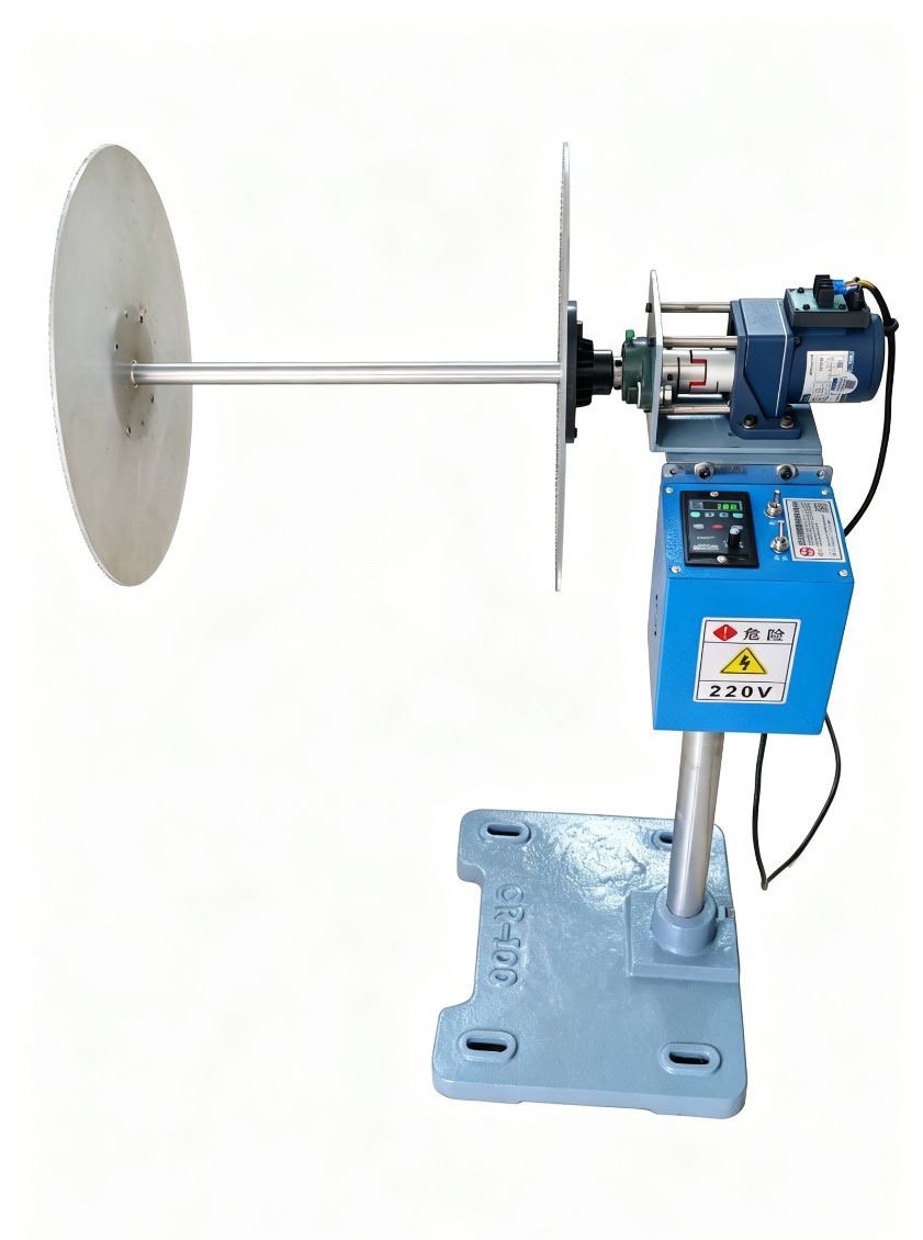
Flexible floor-mounted unit
Use a separate stand when the existing machine should not carry the rewinder or when the take-up position needs more placement freedom. For a compact standalone rewinder that winds film, release liner or interleaf paper onto paper cores beside the line, see the protective film rewinder machine.

Take up film during uncoiling
Mount the unit close to the decoiler when the film should leave the coil before downstream leveling or feeding. This is the usual decoiler with film rewinder layout: the film winding function is added to the decoiler, and the film is peeled at the same speed as the coil unwinds.

Fit a leveler or feeder position
Use a custom bracket when the practical peeling point is beside or above an existing straightener, leveler, or feeder.
Technical configuration
Buyer-safe data for early project matching
Only confirmed values are listed. Drive size, support dimensions, shaft structure, and final winding behavior are selected after line data review.
| Selection item | Available configuration | What Henli needs |
|---|---|---|
| Material width | up to 1300 mm | Maximum strip and protective-film width |
| Running speed | Matched to the production line | Maximum normal line speed |
| Control method | Independent torque adjustment | Film condition and required winding pull |
| Installation | Standalone or integrated | Photo or video of the chosen position |
| Take-up direction | Configured to the strip path | Material travel direction |
| Power supply | Matched to the destination factory | Available voltage and frequency |
| Metal materials | Stainless steel, aluminum, copper, galvanized steel, pre-painted metal | Material and surface-protection requirement |
Important: final configuration depends on width and speed together. Send the maximum production condition rather than an average working value.

Drive and adjustment
Independent control keeps setup practical
The rewinder has its own controller. The operator sets a suitable winding torque for the protective film instead of relying on a fixed public speed or one universal motor specification.
- Increase or reduce the winding pull for the real film behavior.
- Match the drive selection to material width and maximum line speed.
- Prepare the take-up direction around the actual strip route.
- Keep motor power and reduction details inside the project selection process.
Material applications
For surface-sensitive metal strip with removable protection film
Typical use is to remove the temporary protective film, such as PE, PVC or laser-cutting film, before it reaches the next processing point, while keeping the waste film controlled and easier to handle. Peeling it on the line keeps loose film out of the leveler and feeder and stops film residue from reaching the stamping die.

Real application
Let the strip path determine the take-up position
This close view shows the protective film leaving the material before the next processing point and winding into a controlled roll.
Real installation evidence
Mount the rewinder where the film path works best
Photos of the target machine allow Henli to position the support, controller, and take-up shaft without forcing one repeated bracket onto different equipment.

Remove film as the coil unwinds
A top-mounted unit keeps the take-up path close to the coil and away from downstream leveling or feeding components.

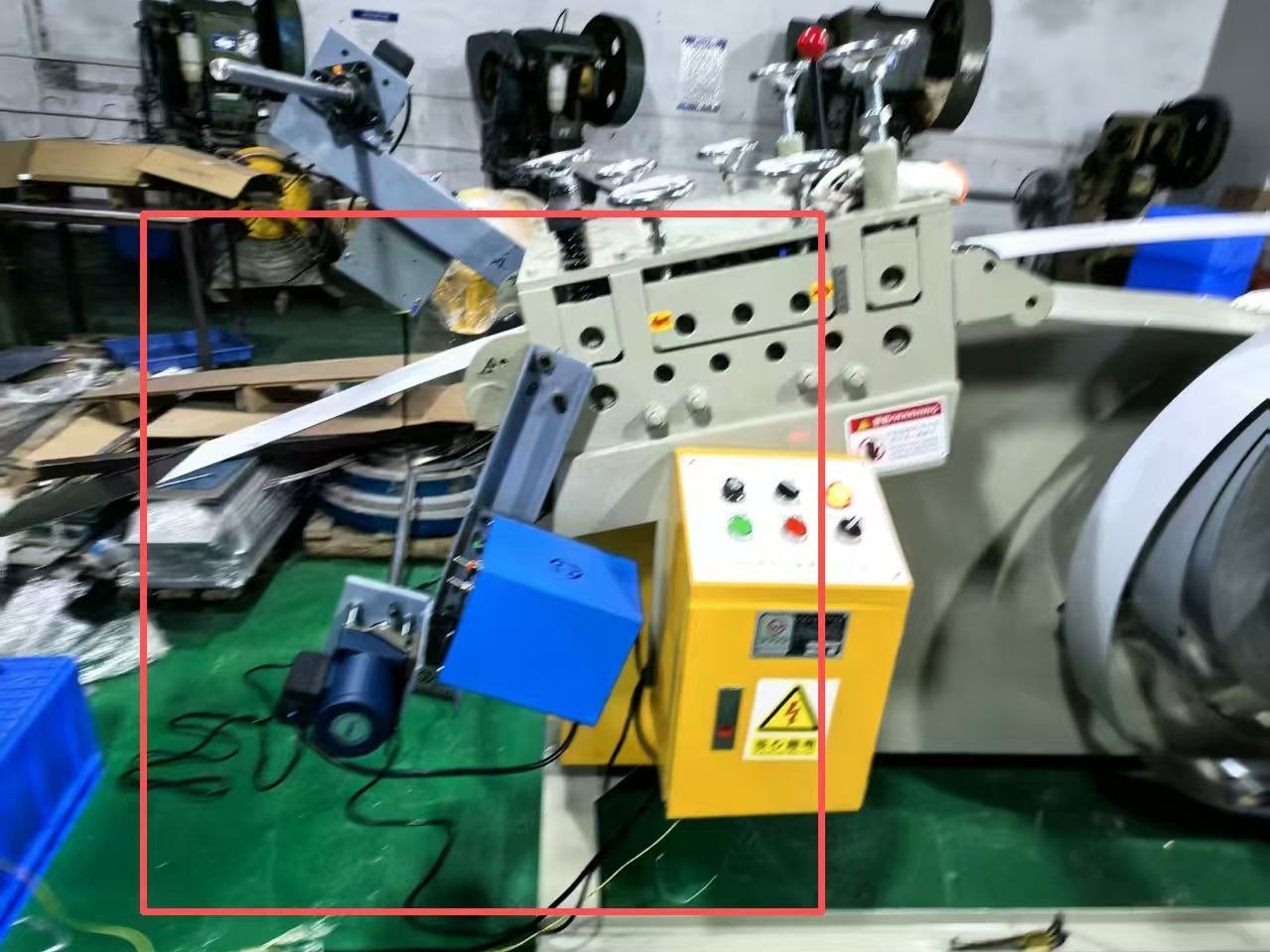
Use the practical downstream peeling point
A side or overhead bracket can place the rewinder near the strip entry when the existing line layout makes this route more suitable.
Video references
See film take-up during real coil processing
These Henli workshop videos show automatic film peeling during uncoiling: protective film leaving the metal coil and winding above the decoiler in practical line layouts.
Film peeling during uncoiling
Protective film is separated from the coil surface and collected above the decoiler.
Mirror-finish stamping line example
A real workshop reference for controlled film removal before downstream press work.
Product gallery
Product and workshop configurations for project matching
The visible shaft and reel styles are engineering configuration choices. Buyers only need to provide the line data and installation target.
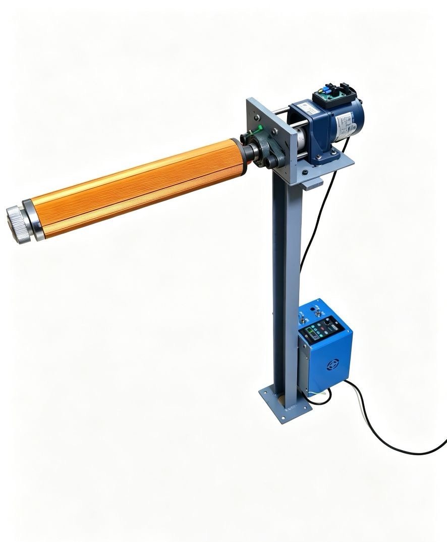


Quote preparation
Send one installation photo and the real production data
Henli will use the information to choose a practical take-up width, drive setup, support bracket, and installation direction. HENLI builds the device in its own factory; standard configurations usually ship within 7 days and carry a 2-year warranty.
Quotation data checklist
- Metal material
- Maximum strip width
- Maximum line speed
- Target machine
- Installation photo or video
- Strip travel direction
- Factory voltage / frequency
- Single-side film position
FAQ
Questions before selecting a protective film rewinder
Use these answers for early project screening. Final drive and mounting details are confirmed after Henli reviews the production line.
What is the maximum material width for this protective film peeling device?
The device can be configured for material widths up to 1300 mm. The actual take-up span is matched to the strip and protective-film width.
What information is required before quotation?
Send the metal material, maximum strip width, maximum line speed, target installation machine, installation photo or video, strip travel direction, and factory voltage.
Can the device be added to an existing decoiler, uncoiler or production line?
Yes. Henli can prepare a standalone floor unit or an integrated support for an existing decoiler or uncoiler, leveler, straightener, or feeder after reviewing the chosen installation position.
Is this the same as a decoiler with film rewinder?
It is the unit that gives a decoiler its film rewinding function. It can be mounted on the decoiler so the film leaves the coil as it unwinds, fitted at a leveler or feeder, or set up as a floor unit. For a compact standalone rewinder beside the line, see the protective film rewinder machine.
Why remove the protective film before leveling, feeding or stamping?
Loose film can be drawn into leveler or feed rollers, and film residue that reaches the die can jam or damage it. Peeling the film automatically on the line also means no worker has to stand at the uncoiler peeling it by hand.
Does the film take-up keep pace with the line?
Yes. In every installation the film is peeled at the same speed as the strip moves, and the operator only sets the winding torque at the unit's own controller; nothing is added to the press or feeder program.
Which metal materials can use this film take-up device?
Typical applications include stainless steel, aluminum, copper, galvanized steel, and pre-painted metal strip supplied with removable surface-protection film.
Which protective films can it peel?
PE, PVC and laser-cutting protective films can all be peeled and wound. The same take-up can also collect interleaf paper or release liner. Send the film type and whether it is on one side or both sides.
How is the winding pull controlled?
The unit uses an independent controller with adjustable winding torque. The operator sets the pull to suit the film behavior; excessive pull can be reduced at the controller.
What if the metal strip has protective film on both sides?
Send the film position and strip-path layout for engineering review. A separate take-up unit may be required for the second side, depending on the line arrangement.
What take-up roll size does it handle?
The take-up shaft and roll diameter are matched to the decoiler, the coil and the film on your line, so there is no single fixed size. Send the coil width and a photo of the decoiler or line for the configuration.
What affects the price of a protective film peeling device?
Mainly the material width, the installation position and bracket (decoiler, leveler, feeder or floor unit), the maximum line speed, whether one or both sides carry film, and the factory voltage. Send these with an installation photo for a quotation.


