
Custom coil handling for existing or new decoilers
Hydraulic Coil Loading Car for Decoilers
HENLI builds hydraulic coil loading cars for decoilers and uncoilers, including single-head, double-head, 2-in-1 and 3-in-1 press feeding systems. Each car is matched to coil weight and dimensions, mandrel center height and rail travel for a new installation or a retrofit.

Overview
What Is a Hydraulic Coil Loading Car?
A hydraulic coil loading car supports a metal coil, lifts it until the coil bore aligns with the decoiler (uncoiler) mandrel, and travels along rails to position it for loading. Also called a coil loading trolley or coil loading cart, it combines lifting and guided travel at the entry to a coil processing line.
Retrofit an Existing Decoiler
If the original decoiler was purchased without a loading car, Henli can engineer a separate coil car around the existing base, spindle position, available approach distance, floor condition, and electrical or hydraulic interface.
Load and Align the Coil
The V-shaped saddle supports the coil, the hydraulic cylinder raises it, and the motorized undercarriage travels along floor rails. A handheld pendant lets the operator watch the coil I.D. and mandrel during final inching and alignment.
Match the Real Coil Range
Capacity alone is not enough. We support custom coil and material widths from 100 to 2,000 mm, then confirm maximum weight, I.D., O.D., mandrel center height, lift range, safety-post clearance, rail travel, and interference around the decoiler base.
Workshop demonstration · 1 min 43 sec
Watch the Coil Loading Trolley in Operation
See hydraulic raising and lowering, forward and reverse rail travel, and the handheld pendant controls in this HENLI workshop demonstration.
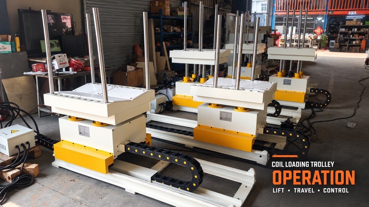
Power supply, hydraulic setup and control arrangement shown in the video apply to the demonstrated units. Confirm these details for your order.
Compatibility
Coil Cars for Decoilers and Complete Press Feeding Lines
A coil loading car can serve a standalone decoiler or the decoiling section of a straightening and feeding line. The uncoiler loading car must match the actual mandrel position, approach direction, rail path and surrounding clearance.

Standalone Decoiler + Coil Car
A separate coil car travels directly to the mandrel centerline of the decoiler. This configuration is suitable for a new installation or a retrofit where the existing decoiler base, anchor points, and loading direction must remain unchanged.

Decoiler Straightener + Coil Car
This is a 2-in-1 decoiler-straightener, not a standalone decoiler. The loading car must align with the mandrel while maintaining clearance from the straightening section, hold-down arm, coil guides, and control side.

3-in-1 Decoiler Straightener Feeder
The decoiler, straightener, and servo feeder are integrated into one compact machine. The coil car is customized around the combined machine base, decoiler mandrel height, threading path, and press-line operating space.

Separate Decoiler, Straightener & Feeder
In a split press feeding line, the decoiler, straightener, and feeder are separate machines. The coil car serves the decoiler while rail position and loading access are coordinated with the downstream loop, straightener, feeder, and press.

Why the raised saddle or spacer block?
Large Coil O.D. Can Require a Higher Loading Surface
A large coil outer diameter normally requires the decoiler mandrel centerline to be higher so the coil clears the floor and machine base during rotation. When the mandrel is raised, the custom coil car must also reach that higher centerline.
The added saddle block or raised support is therefore used to bring the coil center up to the decoiler spindle position. It is not added because the coil inner diameter is small. Coil I.D. affects mandrel fit and expansion range; coil O.D. and spindle height determine the vertical loading geometry.
- Coil O.D.Controls the coil radius and floor/base clearance.
- Mandrel heightSets the target coil centerline during loading.
- Saddle rangeMust cover the lowest and highest coil center required.
Coil retention
Two Retaining Structures for Different Coil Loads
Both designs retain the coil on the saddle. The correct structure depends on coil weight, width, material thickness, center of gravity, and the risk of the coil leaning during travel or lifting.

Raised and Reinforced Retaining Arms
The orange side arms in this project photo show the standard retaining structure. The V saddle naturally centers the coil, while the taller and thicker retaining arms add protection for common loading duties without interfering with the coil bore or decoiler mandrel. This particular project also includes a separate raised saddle module.
- Load rating confirmed for the supplied configuration
- Adjustable to coil width and clearance
- Simple removal and everyday operation

Removable Insertable Retaining Posts
The workshop photo shows long removable posts passing through the V-saddle support. Post diameter, insertion depth, spacing and platform structure are selected for the actual coil weight, width and stability requirements.
- Removable posts for the loading arrangement
- Post positions coordinated with coil width
- Retaining structure checked against coil data
Workshop details
Hydraulic Lift and Rail Travel
Two close views show how the lifting platform, guide columns and rail base fit together on the photographed units.

Lift Cylinder and Guide Columns
The close-up shows the central hydraulic lift cylinder, surrounding guide columns and cable carrier. Confirm the load rating and lifting range for the ordered configuration.

Rail Base and Traveling Carriage
The side view shows the rail bases and lower travel assemblies, with the platforms at different heights. Rail length, loading direction and clearances are matched to the decoiler layout.
Technical range
Hydraulic Coil Car Specifications
Use these values as a first-pass guide. Every retrofit and heavy-duty coil car is finalized from the actual coil and decoiler drawings.
Final capacity, height, and rail travel are engineered for the project.
| Carrying capacity | 3,000–20,000 kg6,600–44,000 lb, customized to the coil and decoiler |
|---|---|
| Horizontal travel speed | Approx. 4 m/minApprox. 13.1 ft/min, with inching control for alignment |
| Typical lifting stroke | 300 mm11.8 in; custom stroke and minimum/maximum saddle height available |
| Custom coil/material width | 100–2,000 mm3.9–78.7 in; platform and support geometry are engineered to the actual width range |
| Rail travel | 2,000 mm project reference78.7 in project reference; custom to the approach distance and floor layout |
| Coil support | V-shaped saddle or double-roller support; wear-resistant contact surface available |
| Lift guidance | Four guide columns for stable vertical movement under load |
| Horizontal drive | Geared motor and chain/sprocket drive on floor rails |
| Hydraulic source | Shared with the hydraulic decoiler or supplied with an independent power unit |
| Operator control | Handheld pendant for forward, reverse, raise, lower, and controlled inching |
| Retention options | Raised/thickened retaining arms or long insertable through-posts for heavy coils |
| Compatible equipment | Single-head decoiler, double-head decoiler, hydraulic uncoiler, 2-in-1 decoiler straightener, and 3-in-1 feeder |
Why “300 mm stroke” is not the whole answer: the same hydraulic stroke can produce different usable coil ranges depending on the fixed saddle height, V-saddle geometry, coil O.D., and the decoiler mandrel center height. We calculate the complete minimum-to-maximum coil-center envelope before releasing the drawing.

Real retrofit workflow
Five Coil Cars Standardized for Different Existing Decoilers
In a five-unit retrofit project, the customer had existing uncoilers with different base interference and spindle heights. HENLI checked the drawings, standardized the main dimensions where practical, and kept one unit’s rail and height geometry project-specific.
Before fabrication, Henli can provide a dimensioned drawing or DWG for review. Production begins after the loading height, base clearance, rail position, retaining posts, and operating direction are confirmed.
Quotation checklist
Send These Details for Coil Car Selection
Rough photos are useful, but dimensioned data prevents rail, base, stroke, and safety-post interference during installation.
Project photos and drawings
Custom Coil Loading Car Gallery
Workshop, installation, and engineering references for coil car retrofit and new line projects.


Related equipment
Build the Complete Coil Handling System
FAQ
Hydraulic Coil Loading Car Questions
Answers for buyers adding a coil car to an existing decoiler or specifying a new coil handling system.
Can I add a coil loading car to an existing decoiler?
What other names are used for a coil loading car?
Is a coil loading car the same as a coil transfer cart?
Does this coil car turn a coil from vertical to horizontal?
Can one design work with both single-head and double-head decoilers?
Why does a custom coil car sometimes need a raised saddle block?
Which retaining structure is better for 8- or 10-ton coils?
What coil width can the loading car handle?
Is a 300 mm hydraulic lifting stroke enough?
Does the coil car need its own hydraulic station?
How are the floor rails installed?
What information is required for an accurate coil car quote?
Need a Coil Car for an Existing Decoiler?
Send the decoiler drawing and your coil data. Henli will check mandrel height, base interference, rail travel, lifting range, and the correct retaining structure before preparing a custom proposal.
Not sure how much your coil weighs?
Enter the material, outer diameter, inner diameter and width to estimate coil weight and PIW. Use the result as the first load-class check, then send the complete coil and line data to HENLI for a custom decoiler selection.


